My Latest Project - the ME Beam Engine
January 2023
Looking for a new project I had thought about building the 'Lady Stephanie' beam engine and I had even bought the drawings from Reeves. It was a couple of weeks after that I sat down to study them. What a mess! They must have been 4th generation photocopies before they were commited to a digital file.
They were 'blotchy' and in many areas so indistinct that they were impossible to understand.
I complained to Reeves, but they refused point blank to either replace or refund, claiming that it was more than 2 weeks since I bought them and that there was nothing wrong with them.
Suffice to say that I will NEVER use Reeves again and from what I gather from other model engineers, my experience is anything but uncommon.
This quite put me off 'Lady Stephanie' and left me without a project.
A short while after this, I was sitting in the clubhouse when another member came in and said to me "you like stationary engines, why not try this one" and dropped a set of drawings on the table. It turned out that these were for the ME beam engine.
So I set to, looking for a set of castings. Apparently there are two suppliers, one is Reeves (no, certainly not!); the other is Brunel and it seemed - from what I was told by various model engineers - that they were unreliable too.
The alternative, of course, was to build it without castings. A bit of a daunting task, but do-able and this was the route I decided to take.
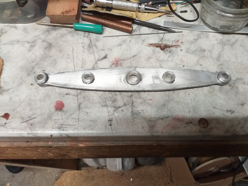
While I was making up lists of stuff I needed (and crying over the price!) I decided to start on the beam.
I used some 4mm aluminium plate for the main part and turned up the (2 part) bushes. I got these fitted using JB Weld and then I fitted the capping strips again with JBW. I also turned up some bronze bushes and inserted them into the ally bushes.
It still needs a bit of work, but it's well on the way.
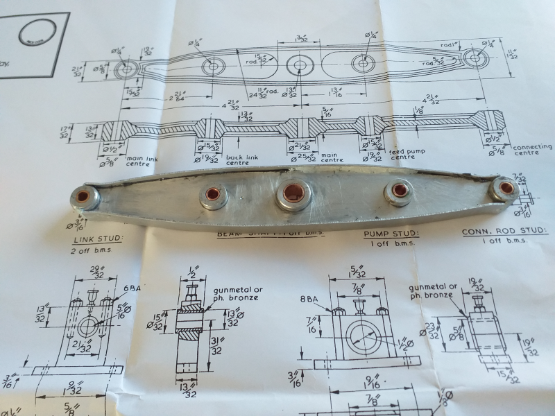
Beam construction.
A bit more work and a coat of paint and its starting to look like a beam.
Well, that club member has been in again and this time he brought me a partly built ME beam engine. The base, column and entablature have all been completed and the whole thing mounted on a plinth. There are rattling sounds from the plinth, so I think there might be a few bits inside.
Can't wait to get going, but it's Harrgate ME Exhibition this weekend, so everything is on hold.
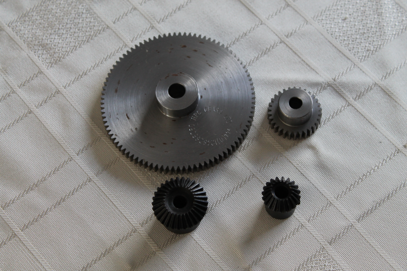
In the meantime I have sourced all the gears - the bevel gears are Chinese and the pinions are British - so I'm ready on that front too.
So I opened up the plinth and this is what I found
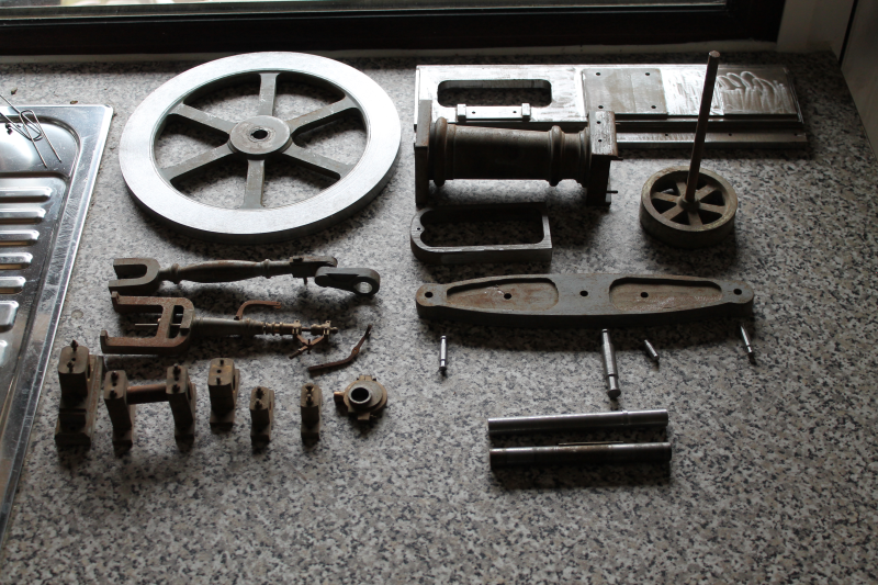
Most of the parts have been given a coat of primer, but there's also a lot of rust. They must have been lying around someones workshop for a very long time.
They don't look to bad but time will tell just how well they've been made.
I thought I might start on the flywheel, so I mounted it on a mandrel and popped it onto the lathe. Wobbly! Turns out the bore isn't parallel, so I'll have to mount it on the faceplate and sort it out.
Ok, the bore is now parallel and the rest of the flywheel has cleaned up a treat - except for the spokes which will have to get the paint removed and the rust cleaned out. I've also turned up the crankshaft and tried the flywheel on it. Now that it's a good fit, there's hardly any runout.
I've been busy trying to get all the rust and old paint off the various bits and it's been hard going, but at least now I can see the metal.
When I had a close look at the governor, I realised that whoever had started on it hadn't done a very good job. The upper column is screwed into the lower 'leg' piece and it's not straight, consequently, the shaft is very hard to turn. Not ideal. I mounted it with the legs in the 4 jaw chuck and it was obvious that there was a problem. Now I think the maker must have realised this and had tried to get around it by drilling the whole thing to 3/16" and bushing it. (It needs to be drilled for a 1/8" shaft). Then I think he's drilled it from either end! Ok, so knock the bushes out and make some new ones. Mounted in the 4 jaw again and set up as near square as I can get it and drill right through with a long 3mm drill - followed up with a 1/8" from either end. Now the shaft turns quite freely.
Now for the fiddly bits. One arm and one link had been made, but the link was too short. I made all 3 parts together on the same piece of 1/8" square rod. Cutting them all free, I then had to fit them all. As they are held together by 10BA bolts there was much bad language! Eventually I got them all assembled and working.
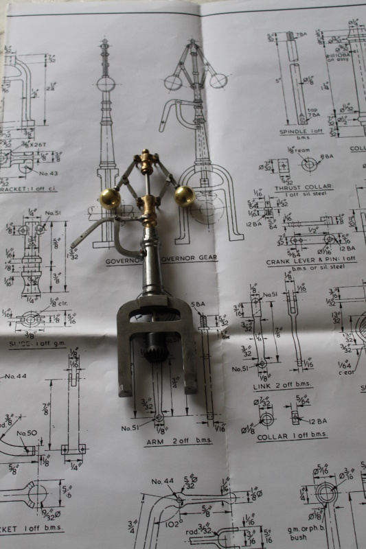
The assembled governor - still needs a bit more polishing.
Next I started on the main pillar. Gave it a good clean and polish and it's starting to look ok.
It had the studs for the bearings in place and they were rusty, so I thought take 'em out and throw them away. Easier said than done! I had to heat them up first and then grab them with a spare small drill chuck (pliers were no good) and I managed to remove 3 of them, but the last one snapped off.
Mill off the remainder of the stud and re-drill and tap.
That's when I realised, once again, that whoever had made these parts really hadn't a clue.
When I checked the dimensions of the part against the drawing, they bore no relation to each other. The top square section was oversize in both directions and the stud holes were anybody's guess!
I'm going to have to re-machine the top section and I won't be able to get all the features shown on the drawing. At least he got the height right!
Lets get on with something else while I think about the pillar.
The drawing calls for the large ring gear to be 'crossed out' (thats making holes in it to give it spokes). So, as I've never done this before, I thought I'd have a bit of practice.
Problem No. 1. My rotary table is only 4 inch. Not big enough to be able to clamp the material in place.
Now, I've been thinking for a while about getting a bigger one, so I guess I'll have to bite the bullet. The original was a 'Vertex' so I looked at prices. Oh dear. Can't justify a new Vertex, so what about the rest? I recently got a new milling vice and that was of Vevor manufacture. It's proved to be well made and functional. They also make rotary tables and the spec' looks ok. So I ordered a new 6 inch Vevor rotary table.
Well, it's arrived and I'm pleased to say that it does what it says on the tin! Pretty hefty beast, though.
I've had a bit of practice at crossing out the big gear - no, not on the real one , just on some scraps of plywood. I think I've found a workable solution which will give me straight spokes, so that should look ok.
I've also been busy making T nuts and a few other bits and pieces for the table; isn't it amazing how the time just flies by!
Now, the problem with the pillar sent me back to all the bits I had inherited, to see what other disasters were lurking there. Yes I found a few more. I think the chap who made them had a rubber measuring stick. The connecting rod looked ok until I started to measure it. The only correct dimension was its major diameter! I decided that it would be easier to make it in two parts, the fork and the rest of it. As it was unuseable, I cut off the fork plus about 20mm, then mounted it in the 4 jaw. I turned down the end and threaded it M6. Now I only have to make the rest of it from a bit of 5/8" diameter BMS.
Back to the pillar and what to do with it. I machined the head to the correct dimensions and then went on to see to the erroneous stud holes. I drilled them out to 1/4" and loctited a bit of rod into each one. After the glue had cured, I milled them all flat. I did the same with the entablature mounting holes as they were equally bad. Then I set too, putting the holes in the right places.
Now for the entablature. Yes, you guessed right; another bin job. I made a new one in aluminium - even cutting the groove around it. Amazing what you can do with a rotary table!
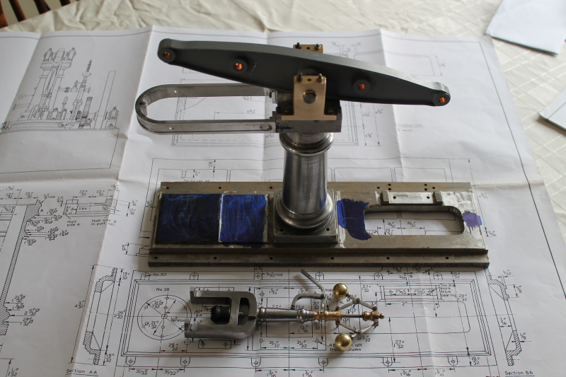
The pillar assembly. Looking good so far.
Ignore the base plate; another scrap job.
On with the motley. Now for the connecting rod. As I had saved the fork end already I only needed a length of 5/8" round BMS to make the rest of it. Just a nice turning job. I also had to drill and tap one end at M6. Would you believe it, I snapped the tap! Good job its got plenty of spare at each end. Once turned, it had to be fluted with 4 flutes of 1/2" diameter. I don't have a 1/2" ball-nosed cutter, so I used a 1/4" one and made 6 flutes. This new rotary table is really coming in useful! I left plenty of spare at the big end so I'll be able to adjust for correct length later.
It's not quite finished yet, I still need to decide whether to follow the drawings and make the rather complex bearing arrangements, or settle for something simpler. It still needs a good polish, but I'm quite happy with it so far.
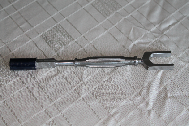
The connecting rod - almost finished.